Incline Drag Conveyors
The incline series of Schlagel Powerflow conveyors is a continuation in our line of “En-Masse” conveyors introduced in 1970. This series is used when the normal 10 degree maximum incline of a standard series conveyor is not adequate to meet your needs.
Our incline conveyors allow a great deal more latitude in the design and layout of a bulk material handling system by enabling you to “bend” a conveyor up and over an obstacle.
You should keep in mind that while an incline style conveyor can offer a great deal of flexibility in your layout, it is better to try using our standard series of conveyors when possible. Our standard style gives you better efficiency at a lower cost and with less maintenance.
This series of conveyors differs from our standard conveyors in many ways. The trough area utilized for material conveying is only about 40 percent compared to approximately 85 percent in the standard series. This results in a larger trough housing for a particular capacity requirement.
The incline series conveyors cannot be flood or choke fed unless a by-pass inlet section of trough is used. If you are going to control feed the conveyor then your inlet must be placed far enough in front of the tail sprocket so that material is not fed directly into the sprocket area.
Figure 1 shows the control fed method by which the capacity is determined by a feeding device such as a bucket elevator, another conveyor or a process machine. The conveyor speed is adjusted so that at maximum capacity the material conveying chamber within the trough is never more than 95 percent full.
Figure 2 shows the flood fed method by which the capacity is determined entirely by the speed of the conveyor. The material conveying chamber is always nearly 100 percent full. It cannot be overfed because the bottom of the by-pass shroud does not allow excess product to enter the conveyor. This feature is very useful when used with a truck or rail dump hoppers, or when reclaiming material from storage bins. It is important to remember that when using a by-pass inlet that full capacity requires material to be fed around both sides of the by-pass shroud.
The horsepower requirements for an incline conveyor are greater than for a standard conveyor for a particular length and capacity. We strongly suggest that you always contact the factory for an actual horsepower requirement due to the many variables that need to be considered for these types of conveyors.
Model I
Model I conveyors are used when you can use a straight conveyor and your angle of incline is between 10 to 50 degrees. They are commonly used on the sloped pitch of a bin top or anywhere the angle is too great for a standard type of drag conveyor.
Model IC
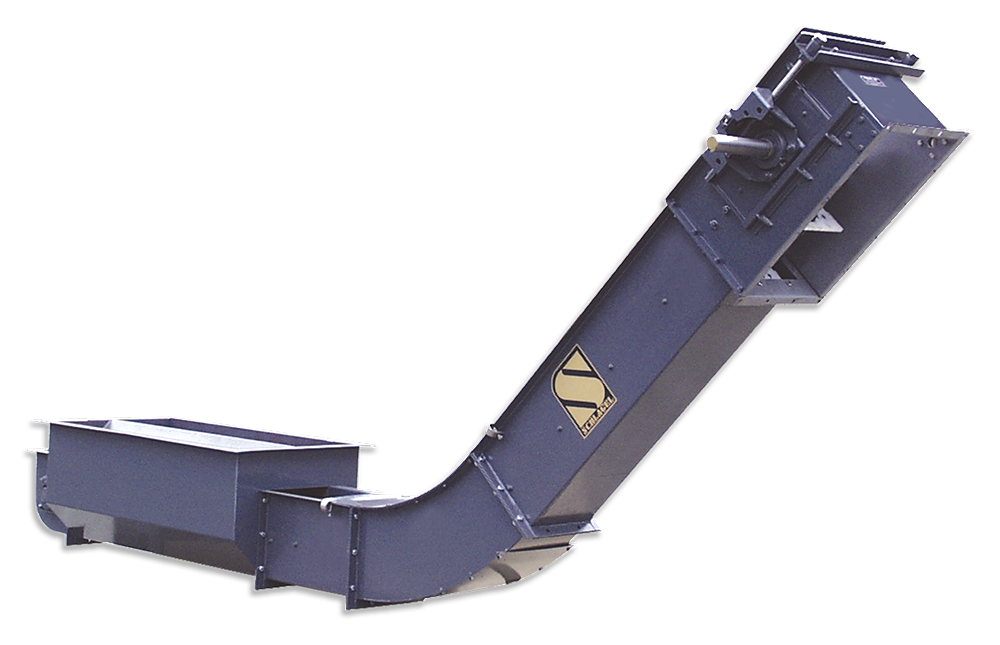
Model IC conveyors are used when you want to convey material horizontally for a certain distance and then curve the conveyor up at angles of 50 degrees or less. These are commonly used for truck or rail receiving where you want to eliminate having the boot of a bucket elevator in a pit. They are also used to gain extra hopper capacity by having a deeper hopper without having to also lower the inlet point of the equipment you are feeding into.
Model DC
Model DC conveyors are used when you want to convey material horizontally for a certain distance, then curve the conveyor up at inclines up to 90 degrees and the reverse curve back to an incline of 50 degrees or less. These would also be used in places that you would select the above ‘IC’ conveyor but have to clear an overhead or ground obstacle that you cannot clear with just one curved section.
Model ICV
Model ICV conveyors are used when you want to convey material horizontally for certain distance and then curve the conveyor up at inclines from 51 to 90 degrees. These would be used in places that you would select the above ‘IC’ conveyor but need the steeper incline ability.
NOTE: All prices and dimensions are subject to change without notice.
Chains are available in many sizes and construction types to suit your particular application. The standard chain design is a roller chain. These are stocked by us in various strengths and sizes from 1.630 inch pitch up to 8 inch pitch. Some of these are also stocked with stainless steel pins or in all stainless steel construction. We also stock a heavy open barrel steel pintle chain as well as having a local source for forged chain which is used in the severest service applications.
Our patented intermediate discharge is available for use on free flowing materials. It is available with manual, air, hydraulic or electric operators. The discharges are weather tight and can easily be field installed. These units feature a compact design that maintains a flush bottom when closed This prevents the product contamination you get when using other types of discharges that use carry over bars and also ensures minimal product being carried past an open discharge.
Troughs are available in several designs as shown in Figure 3. The standard trough is Type 1. Types 2 and 2S are based on Type 1 but have steel liners bolted to the bottom or to the bottom and sides respectively. Type 3 troughs can be constructed using up to 1/2” plate. Normally the sides are on a Type 3 are thinner than the bottom. Abrasion resistant steel is available for Type 3 trough construction or for the liners used on Types 2 and 2S. Abrasion resistant steel will typically outlast mild steel by a factor of 3 to 1 or more. Liners can be shipped loose for field installation or factory installed. The liners are pre-drilled and countersunk when shipped loose. The standard liner thickness is 3/16” for the bottom and 10 GA. for the sides. Liners or bottom plates made from 360 BHN Abrasion Resistant steel is available for severe service use. We will be happy to assist you in the proper selection of trough for the service you require.
By-pass inlet trough sections are available in various lengths and widths to suit your requirements. Certain applications such as a common size of 4 foot long by 2 foot wide while other applications might need an inlet 16 foot long by 8 foot wide in order to have a larger holding capacity.
Grates to fit above a by-pass inlet are available using our innovative formed metal frames that are slotted to accept many different sizes of flat bars. This approach allows us to ship the grate from our factory completely assembled or in pieces that are quickly field installed. You can even supply your own bar and cut to just the size you need in the field. These frames are also available in stainless steel material for use with corrosive materials such as fertilizer.
Shaft mounted drives are recommended because of reliability, efficiency and ease of installation. We can quote conveyors complete with drive, motor mount, guards and motor.
Engineering
The following information is provided as a guide to assist the designer in evaluating the specific operating characteristics and drive requirements for various conveying applications. It is not intended to provide overall engineering for those not thoroughly familiar with the basics of en-masse conveying.
We recommend that all design criteria be presented to factory engineers for evaluation and recommendations.
Conveying Speeds
In general, the maximum recommended chain speed is 160 FPM Total conveyor life increases rapidly as this speed is reduced. Severe duty service conveyors should be limited to approximately 120 FPM or less.
Capacities
When the input is controlled (Figure 1, page 124) the conveyor should be run at 105% of the maximum capacity that can be input. This will assure enough volume within the material chamber to eliminate the possibility of material backup or plugging.
When flooding feeding (Figure 2, page 124) the capacity is exactly that of the Table 1 shown on page 128. In this condition, the conveyor material chamber is nearly 100% full and the capacity is adjusted by regulating the conveyor speed. This type of feeding does require the use of a by-pass style inlet.
Horsepower
There are many factors that must be considered when determining horsepower requirements. Different materials have varying friction factors and weights that will determine the actual horsepower required.
It is beyond the scope of this brochure to show and explain the many calculations required in order to figure the horsepower requirements for the different styles of incline conveyors. We strongly recommend that our sales engineers be consulted for final horsepower and drive selection.
Maximum Lengths
The maximum length of a Powerflow Incline Conveyor is limited by the pull required on the conveying chain. This is a function of the conveyor style selected, material weight per foot of conveyor, the friction factor of the material, elevating height of the conveyor, length and number of inlets, breaking load of the chain, chain safety factors and finally chain wear. Accept-able chain life is normally the most important factor.
It is not within the scope of this brochure to cover all the possible factors, applications and conveyor styles that will make the final determination as to the maximum allowable length. We cannot stress strongly enough the need to consult our sales engineers for final selection.
Inlets
The typical inlet used on an incline conveyor is the by-pass style so that the operator does not have to be concerned with over feeding the conveyor. If a by-pass inlet is not used then care must be taken to be certain the inlet is well ahead of the tail sprocket as well as being careful not to plug the conveyor by over feeding. Unusually long inlets or multiple inlets can require design changes in the conveyor. The factory should always be notified when this is the case.
| Name | Type | Size |
|---|---|---|
| Installation & Operator | manual | 0 bytes |