Screw Conveyor
Screw conveyors are one of the oldest and most versatile types of material conveying devices ever used. The basic principles of how a screw operates have not changed since it was first invented. It is not the purpose of this rather limited bulletin to cover all the styles and factors which have to do with the proper selection and design of a screw conveyor. It is always recommended that all design criteria be given to one of our sales engineers to determine the type and size best suited to your particular application.
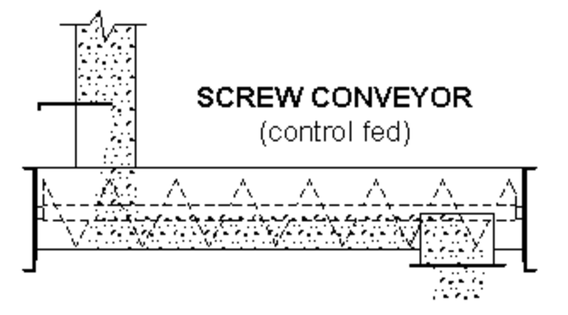
A SCREW CONVEYOR is the generic term often used for any device which contains an internal screw or auger but it also refers to a screw which is being control fed. This means that the flow of material into the screw housing is being regulated or metered by some device such as some other piece of equipment or by means of closing off part of the inlet opening with a slide gate.
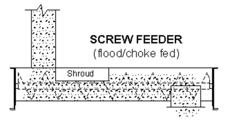
A SCREW FEEDER is a screw which is being flood fed or choke fed. This
means that the flow of material into the screw housing is not being
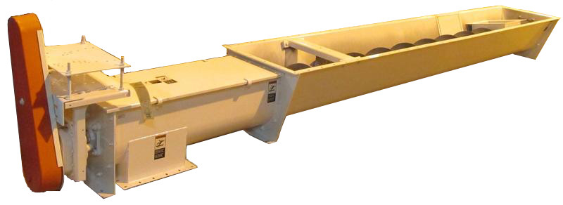
regulated. An typical application of this would be a receiving hopper on top of a screw housing where the truck or rail car gate was opened all the way without any concern of trying to control the volume of material going into the hopper or screw. An example of this style is shown in the drawing on the front cover of this bulletin. This shows a twin screw feeder but a single screw feeder is by far the most common type of feeder.
Each of the two types of screw styles described have extremely important differences in the proper selection and design off all the components needed to meet your conveying requirements.
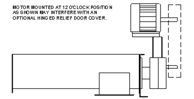
DRIVES are available in several styles with the most common type being the "screw conveyor drive". This is basically a shaft mount drive with a special adapter that allows it to bolt to the typical bearing holes in a screw conveyor housing's end plate. This drive uses a special shaft that has an output extension with holes drilled in it to match the coupling bolt holes in the internal screw section.
Drives are normally located at the discharge end of a screw conveyor but can be used at the inlet end when access to the drive or equipment clearance requires it. The drive being located on the inlet end does not affect the design of a screw.
The HP and RPM requirements for a particular application may result in the necessity of using modified screw components in order to guard against breakage of items such as a shaft or coupling bolts. A screw conveyor requiring a 40 HP drive can be made with a 20 HP drive on each end and a split joint on the internal screw near the middle of the conveyor. This will reduce the load on the components by 1/2 (if split is in center) and may allow you to only run one of the drives if there are multiple discharges on the conveyor.
| Name | Type | Size |
|---|---|---|
| Available Soon | manual | 0 bytes |